
COMPACT-LINE
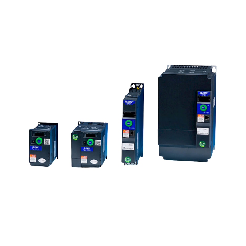
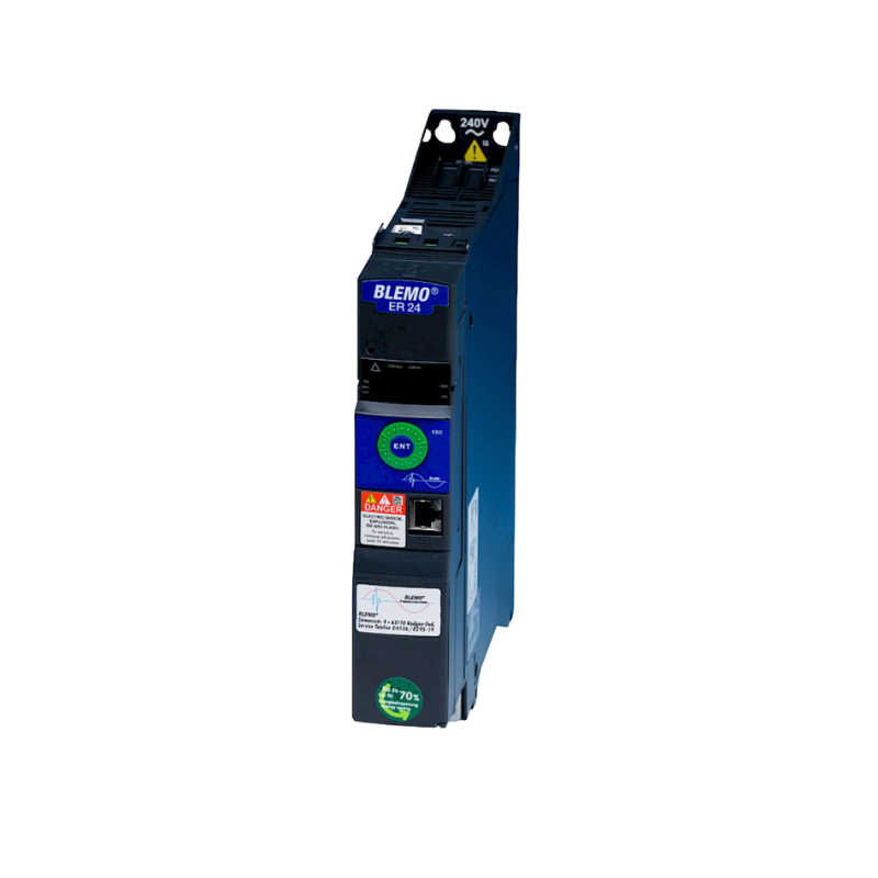
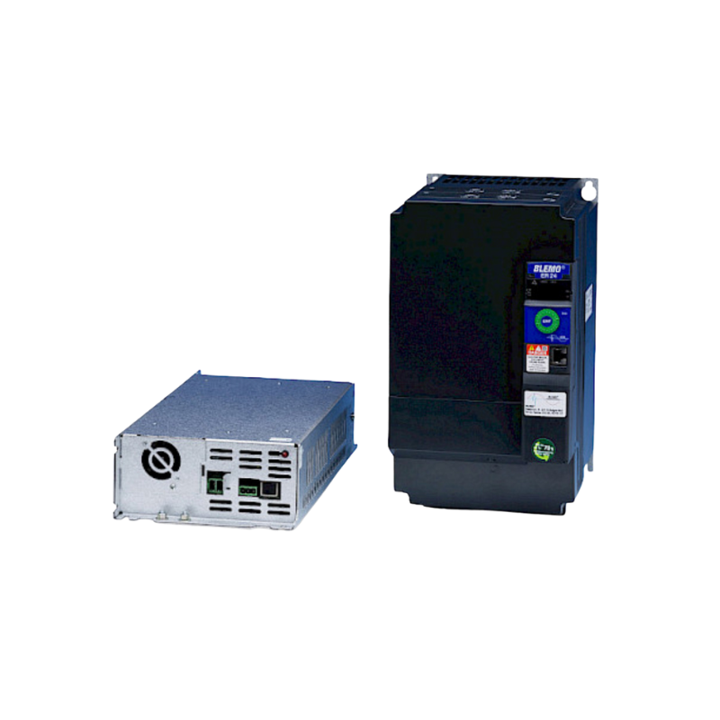
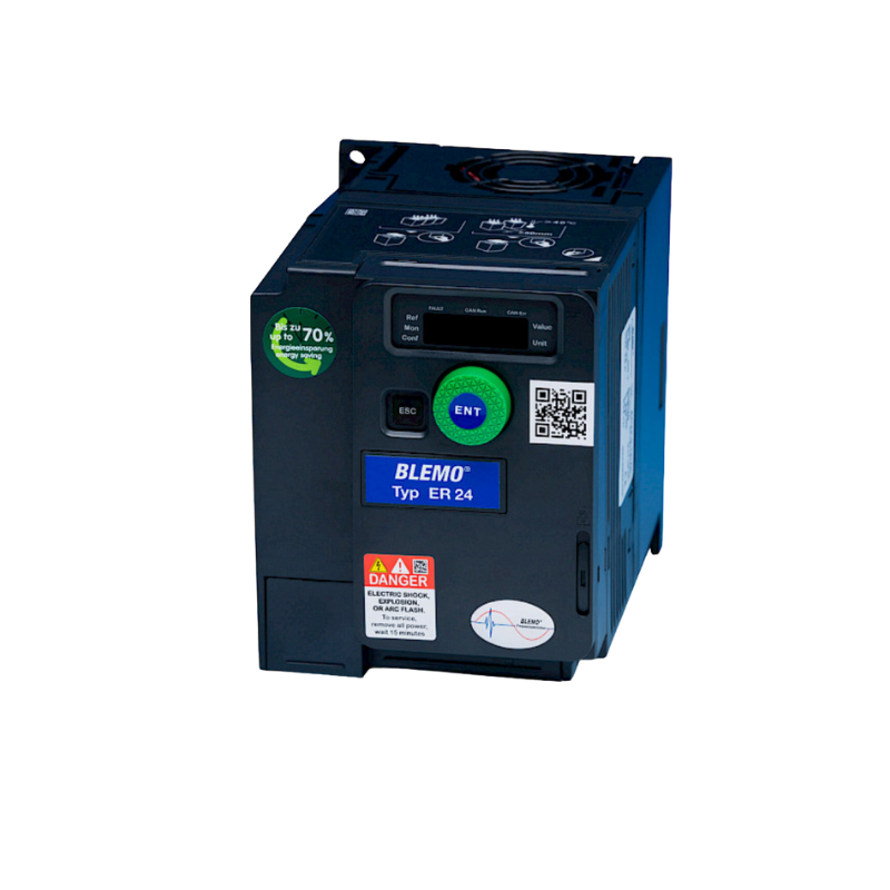
With the new ER24 product range, the successful fusion of the ER23 and ER51 series, you can control synchronous and asynchronous motors efficiently and reliably. The extremely narrow design (ER24B up to 4.0 kW) saves space, while flexible mounting options—vertical, side-by-side, or horizontal—allow for maximum customization.
Integrated safety functions (STO, SLS, SS1, SMS, GDL) and programmable function blocks for timers, counters, comparators, and short automation sequences make the ER24 a versatile all-rounder. In addition, the open-loop synchronous motor function ensures high flexibility in application.


The ER24 is a compact frequency converter for mechanical engineering that impresses in practice with its fast commissioning, high functional density, and easy integration. It reliably controls asynchronous and synchronous motors, offers Modbus and CANopen as standard, and can be expanded with common fieldbuses such as PROFINET or EtherNet IP if required. In addition, there are integrated safety functions such as Safe Torque Off and other safety options, which often reduce the need for additional hardware.
Compared to many other solutions, the ER24 is particularly advantageous if you want to save space in the control cabinet in machine projects, need fast bus integration, and want to map functional safety directly in the drive in a clean manner. This reduces planning effort, wiring, and commissioning time and ensures a robust, service-friendly solution during operation.
The new control algorithm up to 599 Hz for permanently excited synchronous motors without feedback ensures optimized performance and easy connection of the motors.
The sensorless vector control provides full torque from the lowest speeds.
The patented pole wheel position measurement supports all synchronous motor types and also stepper motors.
AUSGEZEICHNETTrustindex überprüft, ob die Originalquelle der Bewertung Google ist. Hallo , ich arbeite seit über 20 Jahre als Industrie Elektroniker in einem Unternehmen und alle Projekte die ich umgesetzt oder umgebaut habe sind mit BLEMO FU‘s wie auch Soft Starter, sehr gute Support, Beratung ich bin sehr zufrieden und hoffe das es so bleibt. Mit freundlichen GrüßenGepostet auf GoogleTrustindex überprüft, ob die Originalquelle der Bewertung Google ist. Ich habe kürzlich den Blemo Frequenzumrichter ausprobiert und war wirklich beeindruckt von seiner Leistung. Dieses Produkt hat meine Erwartungen in vielerlei Hinsicht übertroffen. Zunächst einmal war die Installation des Frequenzumrichters überraschend einfach und unkompliziert. Dank der klaren Anweisungen und der benutzerfreundlichen Oberfläche konnte ich das Gerät problemlos in mein System integrieren. Die Leistung des Blemo Frequenzumrichters ist ebenfalls bemerkenswert. Er liefert eine stabile und zuverlässige Leistung, was zu einer effizienten und reibungslosen Betriebsweise meiner Maschinen geführt hat. Ich habe festgestellt, dass er eine präzise Steuerung der Geschwindigkeit ermöglicht und dabei Energie spart, was sowohl meine Betriebskosten senkt als auch die Umweltbelastung verringert. Darüber hinaus hat mich die Robustheit und Langlebigkeit des Produkts beeindruckt. Der Blemo Frequenzumrichter ist gut gebaut und zeigt keine Anzeichen von Verschleiß oder Überhitzung, selbst nach langen Betriebszeiten. Insgesamt bin ich äußerst zufrieden mit dem Blemo Frequenzumrichter und kann ihn jedem empfehlen, der nach einem zuverlässigen und leistungsstarken Frequenzumrichter sucht. Es ist ein ausgezeichnetes Produkt, das seinen Preis wert ist und meine Erwartungen in jeder Hinsicht erfüllt hat.Gepostet auf GoogleTrustindex überprüft, ob die Originalquelle der Bewertung Google ist. Ich bin sehr zufrieden mit dem Support,bei Fragen bekommt man direkt eine antwort,und die Qualität des Produktes ist hervorragend.Gepostet auf GoogleTrustindex überprüft, ob die Originalquelle der Bewertung Google ist. Top! Alles 10/10 vorallem die Beratung.Gepostet auf GoogleTrustindex überprüft, ob die Originalquelle der Bewertung Google ist. Ich war anfangs eher skeptisch veranlagt im bezug der produkte die hier angeboten werden da ich bereits mehrmals schlechte erfahrungen machen musste die solche Produkte betrifft jedoch kam hier schnell heraus das sich der Kauf der Produkte sehr gelohnt hat meines erachtens nach waren die Produkte sehr hochwertig und dienen seit dem Tag der Lieferung seinem zweck daher kann ich micht nicht beschweren.Gepostet auf GoogleTrustindex überprüft, ob die Originalquelle der Bewertung Google ist. Super Produkt der Motor läuft so sanft damit an oder ändert die Drehzahl das man es kaum merkt. DankeGepostet auf GoogleTrustindex überprüft, ob die Originalquelle der Bewertung Google ist. Super Hilfe im Bezug auf alle meine Fragen rund ums Thema Frequenzumrichter. Sowohl die Beratung als auch die Erklärung liefen äußerst kompetent ab. Vielen Dank!Gepostet auf GoogleTrustindex überprüft, ob die Originalquelle der Bewertung Google ist. Höchste Produktqualität, sie reagieren schnell und professionell auf Anfragen. Sie stehen jederzeit für notwendige Hilfe zur Verfügung.Gepostet auf GoogleTrustindex überprüft, ob die Originalquelle der Bewertung Google ist. Tolles Unternehmen. Super Kompetente Ansprechpartner die immer die richtige Lösung parat haben. Sowohl bei der Auswahl eines geeigneten Frequenzumrichters als auch bei der Inbetriebnahme wird man hier super unterstützt. Vielen Dank an Blemo und vor allem Herrn Thomasch für den hervorragenden Support.
The ER24 combines the successful ER23 and ER51 series. This new product range operates synchronous and asynchronous motors. Below, you can configure your ER24K according to your individual requirements and request a corresponding quote directly from us!
In principle, it is possible to operate a low-power motor with a higher-power frequency converter.
This depends on the ratio between the motor and converter power.
Experience shows that the ratio should not exceed 1:4.
For example, it is not recommended to operate a 0.75 kW motor with a 30 kW BLEMO frequency converter.
This combination can be used for testing purposes, but the motor phase monitoring must be deactivated.
A BLEMO frequency converter can be controlled using a Siemens PLC via Profinet or Profibus-DP.
This requires an additional communication card, which you will find in the frequency converter catalog.
Please note that not all frequency converters support this bus communication.
Connection to Profibus-DP or Profinet is possible with the ER24 and ER41.
Minimum settings for bus operation (direct control of the QW addresses of the ER24 / ER41):
– First, set up the slave ER24 / ER41 xyz in the TIA Portal. Please install the GSD or GSDxml device file beforehand.
– Then select a telegram type in the HW configuration of the ER24 / ER41 and move it to the I/O field.
In this example, we are using telegram 102, which consists of 6 PZDs.
PZD stands for “process cyclic data.” PZDs are data that are to be exchanged cyclically.
This includes status words, target speeds, etc. (see image “EA assignment of PZDs”).
The following four channels are already preset and do not need to be changed. The result during operation can be seen in the “Observation table” image
– The first reserved QW of the PZD address must be used to send the control word (according to Drivecom standard: 16#0006, Stop 16#0007, Motor run 16#000F)
– The second double word sends the target speed (rpm).
– The first IW is read out to read the status word of the ER24 / ER41s frequency converter.
– The second double word is read out to read the current ACTUAL speed (rpm).
– The words should then be declared as variables (see image “Variable declaration”).
– In the frequency converter, the setpoint source fieldbus must be set (see image “Settings ER24 / ER41 setpoint source bus”).
– The addressing of the ER24 / ER41 in the bus must also be set. This naturally differs depending on the bus type.
For Profibus-DP, the address is set to 1-126 (see image “Settings Profibus Addressing ER24 / ER41”),
for Profinet, an address is assigned via PLC: DCP or an address setting in the ER24 / ER41 menu: fixed IP (see image “Settings Profinet Addressing ER24 / ER41“).
German


Your personal contact person