
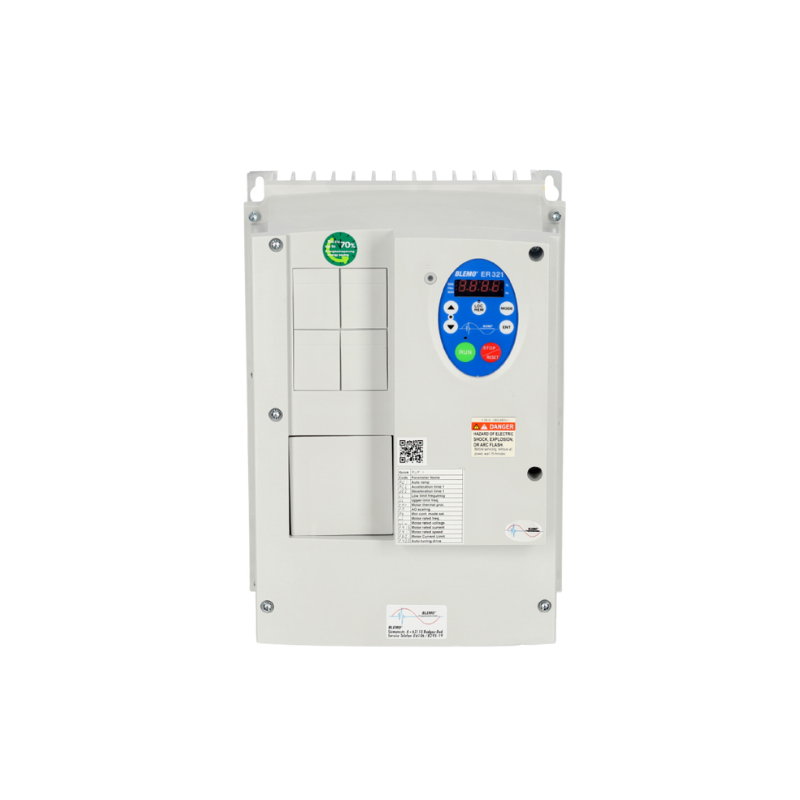
As a further development of the successful ER32, the new product range offers optimum solutions for applications with variable torque – ideal for fans and pumps in building technology as well as in sewage and water treatment plants.
Developed in accordance with current international standards such as EMC and EN 61000-3-12, the series impresses with maximum environmental compatibility, e.g. through lead-free soldering and excellent recyclability.


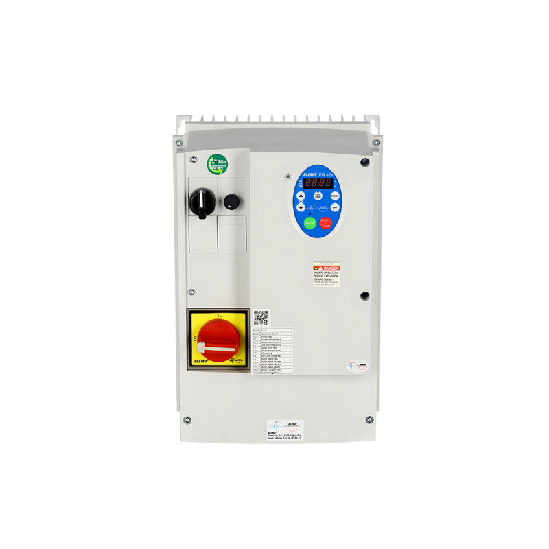
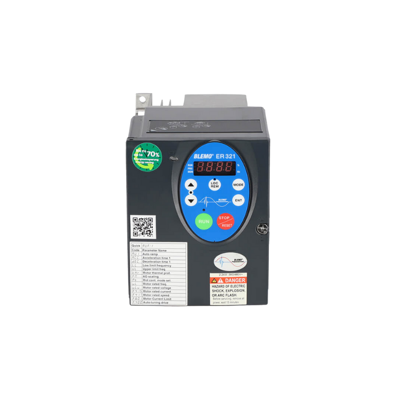
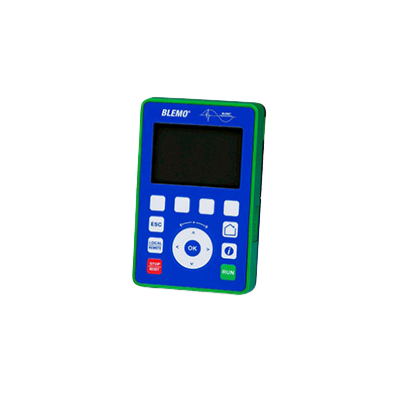
The ER321 is available in two versions ER321-…K, protection class IP21 and ER321-…G, protection class IP54/55 with(-V2) and without(-V1) additional switches. The ER321 is designed with a 4-digit 7-segment display. 7 buttons allow easy programming and control of the device from the display. The Local/Remote button is used to switch between the display and the control terminal strip. A multilingual plain text display is now available as an option.
The ER321 series frequency inverters have a mains filter integrated in the device, are CE marked in accordance with the EU Low Voltage and EMC Directives and comply with the applicable standards for frequency inverters EN 61800-3 and -5-1.
AUSGEZEICHNETTrustindex überprüft, ob die Originalquelle der Bewertung Google ist. Hallo , ich arbeite seit über 20 Jahre als Industrie Elektroniker in einem Unternehmen und alle Projekte die ich umgesetzt oder umgebaut habe sind mit BLEMO FU‘s wie auch Soft Starter, sehr gute Support, Beratung ich bin sehr zufrieden und hoffe das es so bleibt. Mit freundlichen GrüßenGepostet auf GoogleTrustindex überprüft, ob die Originalquelle der Bewertung Google ist. Ich habe kürzlich den Blemo Frequenzumrichter ausprobiert und war wirklich beeindruckt von seiner Leistung. Dieses Produkt hat meine Erwartungen in vielerlei Hinsicht übertroffen. Zunächst einmal war die Installation des Frequenzumrichters überraschend einfach und unkompliziert. Dank der klaren Anweisungen und der benutzerfreundlichen Oberfläche konnte ich das Gerät problemlos in mein System integrieren. Die Leistung des Blemo Frequenzumrichters ist ebenfalls bemerkenswert. Er liefert eine stabile und zuverlässige Leistung, was zu einer effizienten und reibungslosen Betriebsweise meiner Maschinen geführt hat. Ich habe festgestellt, dass er eine präzise Steuerung der Geschwindigkeit ermöglicht und dabei Energie spart, was sowohl meine Betriebskosten senkt als auch die Umweltbelastung verringert. Darüber hinaus hat mich die Robustheit und Langlebigkeit des Produkts beeindruckt. Der Blemo Frequenzumrichter ist gut gebaut und zeigt keine Anzeichen von Verschleiß oder Überhitzung, selbst nach langen Betriebszeiten. Insgesamt bin ich äußerst zufrieden mit dem Blemo Frequenzumrichter und kann ihn jedem empfehlen, der nach einem zuverlässigen und leistungsstarken Frequenzumrichter sucht. Es ist ein ausgezeichnetes Produkt, das seinen Preis wert ist und meine Erwartungen in jeder Hinsicht erfüllt hat.Gepostet auf GoogleTrustindex überprüft, ob die Originalquelle der Bewertung Google ist. Ich bin sehr zufrieden mit dem Support,bei Fragen bekommt man direkt eine antwort,und die Qualität des Produktes ist hervorragend.Gepostet auf GoogleTrustindex überprüft, ob die Originalquelle der Bewertung Google ist. Top! Alles 10/10 vorallem die Beratung.Gepostet auf GoogleTrustindex überprüft, ob die Originalquelle der Bewertung Google ist. Ich war anfangs eher skeptisch veranlagt im bezug der produkte die hier angeboten werden da ich bereits mehrmals schlechte erfahrungen machen musste die solche Produkte betrifft jedoch kam hier schnell heraus das sich der Kauf der Produkte sehr gelohnt hat meines erachtens nach waren die Produkte sehr hochwertig und dienen seit dem Tag der Lieferung seinem zweck daher kann ich micht nicht beschweren.Gepostet auf GoogleTrustindex überprüft, ob die Originalquelle der Bewertung Google ist. Super Produkt der Motor läuft so sanft damit an oder ändert die Drehzahl das man es kaum merkt. DankeGepostet auf GoogleTrustindex überprüft, ob die Originalquelle der Bewertung Google ist. Super Hilfe im Bezug auf alle meine Fragen rund ums Thema Frequenzumrichter. Sowohl die Beratung als auch die Erklärung liefen äußerst kompetent ab. Vielen Dank!Gepostet auf GoogleTrustindex überprüft, ob die Originalquelle der Bewertung Google ist. Höchste Produktqualität, sie reagieren schnell und professionell auf Anfragen. Sie stehen jederzeit für notwendige Hilfe zur Verfügung.Gepostet auf GoogleTrustindex überprüft, ob die Originalquelle der Bewertung Google ist. Tolles Unternehmen. Super Kompetente Ansprechpartner die immer die richtige Lösung parat haben. Sowohl bei der Auswahl eines geeigneten Frequenzumrichters als auch bei der Inbetriebnahme wird man hier super unterstützt. Vielen Dank an Blemo und vor allem Herrn Thomasch für den hervorragenden Support.
German
Russian


Your personal contact person