
The ER24G frequency converter is a further development of the proven ER22G series and was designed for modern requirements in mechanical and plant engineering. It is suitable for both synchronous and asynchronous motors and impresses with its high functionality, easy integration, and reliable operation in demanding applications.
New features include the integrated safety functions STO, SLS, SS1, SMS, and GDL, a direct PTC input, and an integrated synchronous motor function in open-loop mode. In addition, programmable function blocks enable the implementation of logical and arithmetic functions, timers, counters, comparators, and short automation sequences directly in the drive.
For maximum robustness, the protection class was increased to IP66 in version 1 (V1). Version 2 (V2) with integrated switches offers IP65 and is ideal for fast, practical use in the field.


The ER24G is a compact frequency converter for precise speed control of asynchronous and synchronous motors. It reduces energy consumption, protects the motor and mechanics, and can be quickly parameterized.
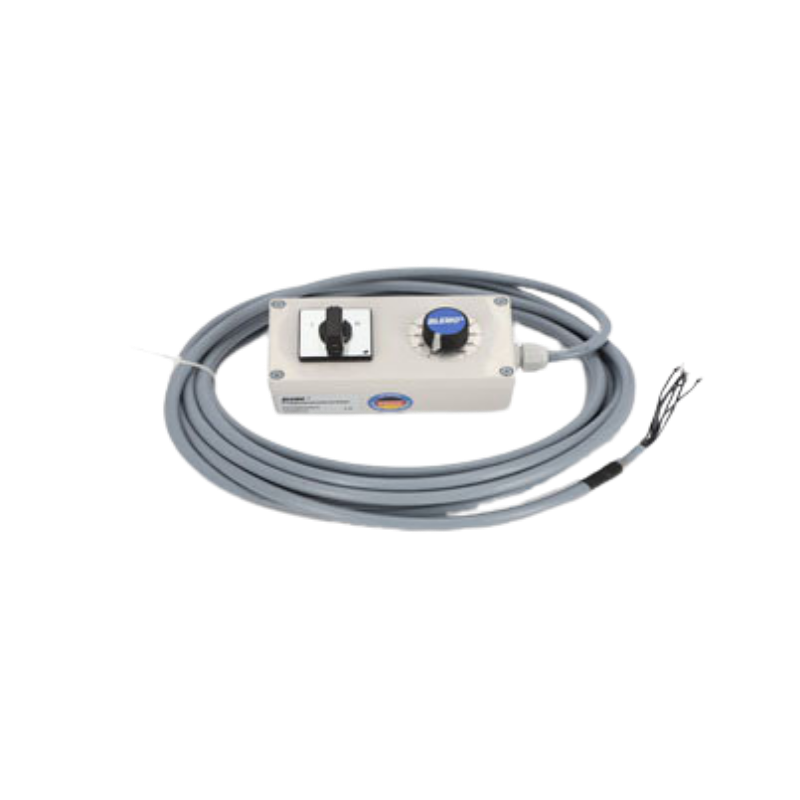
Version 2 is designed as a complete device that is ready for immediate use.
The main switch, setpoint potentiometer, start/stop, and direction of rotation are integrated, which means less wiring is required.

AUSGEZEICHNETTrustindex überprüft, ob die Originalquelle der Bewertung Google ist. Hallo , ich arbeite seit über 20 Jahre als Industrie Elektroniker in einem Unternehmen und alle Projekte die ich umgesetzt oder umgebaut habe sind mit BLEMO FU‘s wie auch Soft Starter, sehr gute Support, Beratung ich bin sehr zufrieden und hoffe das es so bleibt. Mit freundlichen GrüßenGepostet auf GoogleTrustindex überprüft, ob die Originalquelle der Bewertung Google ist. Ich habe kürzlich den Blemo Frequenzumrichter ausprobiert und war wirklich beeindruckt von seiner Leistung. Dieses Produkt hat meine Erwartungen in vielerlei Hinsicht übertroffen. Zunächst einmal war die Installation des Frequenzumrichters überraschend einfach und unkompliziert. Dank der klaren Anweisungen und der benutzerfreundlichen Oberfläche konnte ich das Gerät problemlos in mein System integrieren. Die Leistung des Blemo Frequenzumrichters ist ebenfalls bemerkenswert. Er liefert eine stabile und zuverlässige Leistung, was zu einer effizienten und reibungslosen Betriebsweise meiner Maschinen geführt hat. Ich habe festgestellt, dass er eine präzise Steuerung der Geschwindigkeit ermöglicht und dabei Energie spart, was sowohl meine Betriebskosten senkt als auch die Umweltbelastung verringert. Darüber hinaus hat mich die Robustheit und Langlebigkeit des Produkts beeindruckt. Der Blemo Frequenzumrichter ist gut gebaut und zeigt keine Anzeichen von Verschleiß oder Überhitzung, selbst nach langen Betriebszeiten. Insgesamt bin ich äußerst zufrieden mit dem Blemo Frequenzumrichter und kann ihn jedem empfehlen, der nach einem zuverlässigen und leistungsstarken Frequenzumrichter sucht. Es ist ein ausgezeichnetes Produkt, das seinen Preis wert ist und meine Erwartungen in jeder Hinsicht erfüllt hat.Gepostet auf GoogleTrustindex überprüft, ob die Originalquelle der Bewertung Google ist. Ich bin sehr zufrieden mit dem Support,bei Fragen bekommt man direkt eine antwort,und die Qualität des Produktes ist hervorragend.Gepostet auf GoogleTrustindex überprüft, ob die Originalquelle der Bewertung Google ist. Top! Alles 10/10 vorallem die Beratung.Gepostet auf GoogleTrustindex überprüft, ob die Originalquelle der Bewertung Google ist. Ich war anfangs eher skeptisch veranlagt im bezug der produkte die hier angeboten werden da ich bereits mehrmals schlechte erfahrungen machen musste die solche Produkte betrifft jedoch kam hier schnell heraus das sich der Kauf der Produkte sehr gelohnt hat meines erachtens nach waren die Produkte sehr hochwertig und dienen seit dem Tag der Lieferung seinem zweck daher kann ich micht nicht beschweren.Gepostet auf GoogleTrustindex überprüft, ob die Originalquelle der Bewertung Google ist. Super Produkt der Motor läuft so sanft damit an oder ändert die Drehzahl das man es kaum merkt. DankeGepostet auf GoogleTrustindex überprüft, ob die Originalquelle der Bewertung Google ist. Super Hilfe im Bezug auf alle meine Fragen rund ums Thema Frequenzumrichter. Sowohl die Beratung als auch die Erklärung liefen äußerst kompetent ab. Vielen Dank!Gepostet auf GoogleTrustindex überprüft, ob die Originalquelle der Bewertung Google ist. Höchste Produktqualität, sie reagieren schnell und professionell auf Anfragen. Sie stehen jederzeit für notwendige Hilfe zur Verfügung.Gepostet auf GoogleTrustindex überprüft, ob die Originalquelle der Bewertung Google ist. Tolles Unternehmen. Super Kompetente Ansprechpartner die immer die richtige Lösung parat haben. Sowohl bei der Auswahl eines geeigneten Frequenzumrichters als auch bei der Inbetriebnahme wird man hier super unterstützt. Vielen Dank an Blemo und vor allem Herrn Thomasch für den hervorragenden Support.
The ER24G is our innovation, as it is the further development of the successful ER22G series. This new product range operates synchronous and asynchronous motors. Below you can configure your ER24G according to your individual ideas and request a corresponding offer directly from us!
All page numbers refer to the ER24 Programming Guide.
Switch on the power supply of the inverter without giving a run command (start command +24V and DI1). Observe connection diagram!
Set the following settings:
Set the following parameters in the [SETTINGS (SEt-)] menu:
4. Once all preparations have been completed, the drive command/start command can be wired.
(FU starts and drives off!)
A BLEMO frequency converter can be controlled using a Siemens PLC via Profinet or Profibus-DP.
This requires an additional communication card, which can be found in the frequency converter catalog.
Please note that not all frequency converters support this bus communication.
Connection to Profibus-DP or Profinet is possible with the ER24 and ER41.
Minimum settings for bus operation (direct control of the QW addresses of the ER24 / ER41):
The following four channels are already preset and do not need to be changed. The result in operation can be seen in the “Observation table” image.
In principle, it is possible to operate a low-power motor on a higher-power frequency converter. The ratio between motor and inverter power is important here. Experience shows that the ratio of 1:4 should not be exceeded.
For example, it is not recommended to operate a 0.75 kW motor with a 30 kW BLEMO frequency converter.
This combination can be used for testing purposes, but the motor phase monitoring must be deactivated.
Assuming that the ER24 is in its factory settings, the following settings must be carried out in the stopped state (display: rdY):
German


Your personal contact person