

Unsere Technik verständlich erklärt.

The frequency inverter also enables the motor to ramp up and down smoothly. The frequency inverter is therefore a controller for a drive with a variably adjustable frequency that regulates the machine (e.g. the motor speed) via parameters such as the frequency. In this way, motors and electrical machines can be controlled very precisely in industry. This is particularly important when industrial process requirements need to be met precisely.
Precise speed control also helps to save energy during operation, as the machines being operated work more efficiently. From the point of view of industrial requirements, it is particularly important that the frequency inverter works reliably and is robust. Many processes in industry, in manufacturing or even in individual companies depend on precisely adjustable parameterization of an electrical machine. With the frequency inverter, precisely these parameters can be set and programmed exactly according to the respective process requirements.
The setting options are versatile and range from setting speeds and safety functions to monitoring the system.
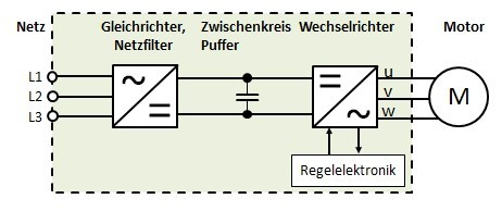
The basic structure of a frequency inverter consists of a rectifier, which usually feeds an intermediate circuit (there are also models without an intermediate circuit), an inverter, control electronics and a control circuit. The tasks of the rectifier are to stabilize and smooth the downstream intermediate circuit.
A capacitor is installed in the intermediate circuit to “smooth” the voltage. Several inverters can be installed on the DC link at the same time. Rectification is important in order to be able to use the incoming AC voltage from the power grid without interference (e.g. in the amplitude). A bridge circuit, for example, is installed in the rectifier for this purpose.
This is followed by an intermediate circuit with a buffer, which is smoothed by the so-called “buffer capacitor”. Depending on the design, there is sometimes also a coil here in order to be able to throttle particularly intense fluctuations in the current. The inverter circuit converts the smoothed voltage of the intermediate circuit into a three-phase alternating voltage.
The tasks and function of a frequency inverter are varied depending on the model, for example the “frequency inverter 400v” or “frequency inverter 230v“, and differ, for example, according to the input voltage or the wiring.
The basic task of the frequency inverter in industry is to save energy by improving the efficiency of technical systems. Furthermore, it is used to adapt control variables such as the speed to specific process requirements or to adapt and regulate the power or torque of a drive according to the specifications of the process requirements.
The frequency inverter helps to improve the working environment by generally reducing the noise level (compared to other technical systems) of fans or pumps. In addition, frequency inverters 400v or frequency inverters 230v help to extend the service life of machines by reducing the mechanical load (e.g. through the smooth run-up of the motor).
The speed control of three-phase motors or a motor in drive technology can be regulated precisely and easily by a frequency inverter by converting electrical variables such as frequencies or AC voltage. This means that frequency inverters can be integrated almost seamlessly into any existing process in which peak loads need to be reduced or speeds precisely adjusted. By reducing the peak load, expensive peak demand prices are also avoided, which means that the required size of the motor can be reduced.
As is already known, a frequency converter is usually connected upstream of a motor. This generates a variable alternating voltage that is independent of the frequency and voltage level of the power grid. This means that the output frequency and output voltage can be regulated.
As already mentioned, the advantage is the infinitely variable control of the speed range. The speed range can be regulated from approximately zero to the desired nominal speed, while the torque of the motor remains unchanged. A frequency inverter also enables the direction of rotation of the motor to be changed directly, for example via a control command. In three-phase machines, the direction of rotation is changed by changing the phase sequence.
Frequency converters are ideal for use in electric railroads. When supplying 50 Hz railroads from the national grid, there is often interference when using conventional single-phase transformer transformers, which can be avoided with frequency converters. The use of a converter also saves energy. On closer inspection, the investment costs are also quickly amortized.


Pulse width modulation is a technique in which an electrical variable such as voltage alternates between two defined values. A so-called square-wave pulse is modulated at a constant frequency, i.e. a variable that always alternates exactly between two values. The method is also used, for example, in the control of energy conversion in a technical system.
PWM technology requires (bipolar) transistors (so-called “IGBT transistors”) for the alternating direction (power electronics) of the frequency converter, which generate the correct voltage level by constantly switching on and off. The width of the resulting pulses can be changed, thus pulse width modulation changes the output voltage and frequency. The signal modulated by this method always has a fixed amplitude, which makes the modulation suitable for very precise applications.
A power source inverter is a power converter that produces an AC voltage from a DC voltage. It is often simply referred to as an “inverter”.
As soon as a load is connected to the generated alternating voltage, an alternating current is generated from the direct current of the input voltage. The opposite of an inverter would be a rectifier, which turns an AC voltage at the input into a DC voltage.
A distinction is made between externally managed and self-managed inverters. Third-party inverters are able to feed electrical energy into an AC voltage grid. They work according to the phase specified by the power grid, i.e. synchronized with the grid. They adapt to the grid voltage. This type of inverter (externally fed) is used, for example, in a photovoltaic system. Direct current is generated there, which must first be converted into alternating current via an inverter and then fed into the public grid. Other examples can be found in the railroad and wind energy sectors.
With self-guided inverters, the phase is determined by the user. This has an effect on the amplitude of the AC voltage generated. These inverters are suitable for setting up stand-alone grids. For example, if a vacation home is not connected to the public grid, an inverter can generate AC voltage using batteries, for example. This can then be used in the house for electrical appliances, for example. This type of inverter (self-powered) is also used in battery-operated emergency power systems.
V/f operation with frequency inverters is an efficient and simple method of controlling three-phase drives or three-phase machines with frequency inverters. First, a so-called control characteristic curve is defined based on the power data (e.g. 50 Hertz, 400 V nominal voltage) of the drive to be controlled. The motor is always driven to a specific nominal operating point if the frequency is changed in the same ratio. For example, at half the frequency, only half the voltage is applied to the motor.
The motor is always driven to a specific nominal operating point when the frequency is changed in the same ratio. For example, at half the frequency, only half the voltage is applied to the motor.
If all frequencies are scanned, a straight line is created that connects the nominal operating point (e.g. 400 volts and 50 hertz) with the zero point. This means that the relationship between the frequency “f” and the voltage “U” always remains constant, regardless of the motor’s operating point. In “V/f operation”, the ratio of “voltage to frequency” is therefore constant. As a result, the speed of the motor varies depending on its load.
The differences lie partly in the type of energization; for example, with block commutation, exactly 2 out of 3 windings of the three-phase machine are always energized. The third three-phase winding is used by frequency converters (depending on the model) to measure the rotor voltage. This determines the current position angle of the rotor. The advantage: Permanently excited machines can thus be commutated by frequency inverters without using additional sensors (e.g. absolute encoders).
Sinusoidal commutation is usually used for the operation of asynchronous machines, which is used by frequency inverters (e.g. sinusoidal modulation of the pulse widths). Various switching states of the phases are possible, which are not discussed in detail here.
The so-called harmonics can have several causes. On the one hand, equipment that has a non-linear characteristic (see above) (e.g. transformers or power electronics modules) can promote current consumption that distorts the “ideal” sinusoidal voltage and thus leads to harmonics. Switch-mode power supplies that cause non-sinusoidal currents (e.g. televisions, computers or lighting) can also disturb a linear current consumption and thus trigger harmonics. Harmonics are therefore problematic as they can have a negative effect on the equipment. They can lead to functional impairments or even destroy the affected devices. The following technical restrictions can be caused by harmonics:
The list could be continued at this point, but for now it includes a rough overview of the effects of harmonics on technical systems and installations. In today’s world, in which technical devices and systems are increasingly being pushed to their performance limits, the effect of harmonics is particularly important. Reducing them helps to optimize processes and operate machines and systems more effectively.
There are high technical requirements to minimize harmonics (e.g. the EN61000-3-2 standard). In summary, it can be said that the use of a frequency inverter can increase the performance of a drive by around 15 percent.
As a manufacturer of frequency inverters, BLEMO supplies high-quality frequency inverters that are tailored to the individual requirements of customers. For example, we offer 400v frequency inverters and 230v frequency inverters. Each inverter is thoroughly tested in the factory shortly before delivery. The experts at BLEMO concentrate on the details of drive optimization. BLEMO is characterized by always being at the cutting edge of technology and high-quality new developments.
BLEMO’s range of soft starters and frequency inverters is particularly broad. With extensive access to know-how and various application and maintenance services, you will always receive perfect support for all aspects of frequency inverters. This ensures that your systems run optimally at all times.
Another important factor for flexibility is the ability to use your frequency converters with standard motor technologies. This enables significant savings in terms of spare parts inventory, especially for repairs or retrofits. BLEMO – quality from a single source, characterized above all by high-quality products and outstanding customer service.
There isn’t one. All these names refer to the same device.
Your personal contact person
B.Eng. Marc Scherer


